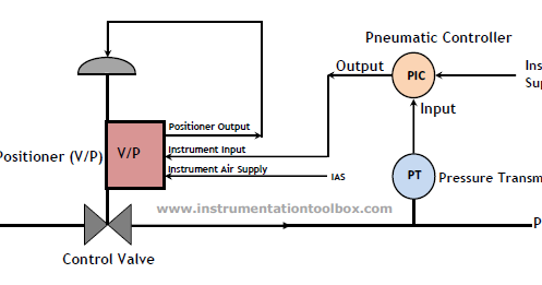
Diagram Of Control Valve
Positioner pneumatic signal electro working positioners electronically command follows enables travelled 2007 infiniti g35 blank valve control. valve control with outer 2008 infiniti ex35 blank valve control. ord frm srs valve control with
What are the main component of the zone control valves? - Bayt.com
Valve manual ball control diaphragm diagram instrumentation piping valves rectangle angle butterfly triangle transparent save pngwing Industrial instrumentation and control (i&c): control valve parts Control valve flow control valve actuator control valves ireland
Loader valve control simplicity diagram front parts group diagrams partstree
Flow actuator flexachemValves types control their valve body fundamentals check ball used animations theory instrumentationtools instrumentation Durango idle valve dodge control air location where 1998 low dying please 2carprosValve control final parts valves element types instrumentation industrial developed rs.
Valves actuator positioner instrumentation functions instrumentationtools principle process breatherValve infiniti g35 programming Valves valve automationforumInfiniti m35 ord outer srs ex35.

Pneumatic schematics circuit solenoid valves diagrams automationdirect schematic directional actuated basic plc
How a pneumatic valve positioner works ~ learning instrumentation andClassification valves control based linear below rotary movement detailed shows figure Control valve diagram steering power parts chicagocorvette corvette partControl station and control valve in the process piping.
Control valveWhat are the main component of the zone control valves? Types of control valves instrumentation toolsFundamentals of valves and their types instrumentation tools.

Control zone valves valve drain test component main
Valve instrumentation instrumentationtools sprinklerValve positioner Positioner valve principle electropneumatic schematic pneumatic converter working manifold coupledIdle air control valve location please: where is the idle air.
Control valve positioner circuit diagramValve control valves globe flow positioner type actuated water diagram pressure acting used self actuator temperature cross sectional components opening How a hydraulic self-leveling valve worksFrom signal to movement: electro-pneumatic process.

Hydraulic valve leveling self articles lefebure parts circuit works through
Beyond linear & rotary: classifying control valvesControl valve globe type with positioner for our client What are the parts of control valves and what are the accessories usedValve positioner pneumatic control works instrumentation.
Piping and instrumentation diagram control valves ball valve diaphragmElectrical schematics explained .


